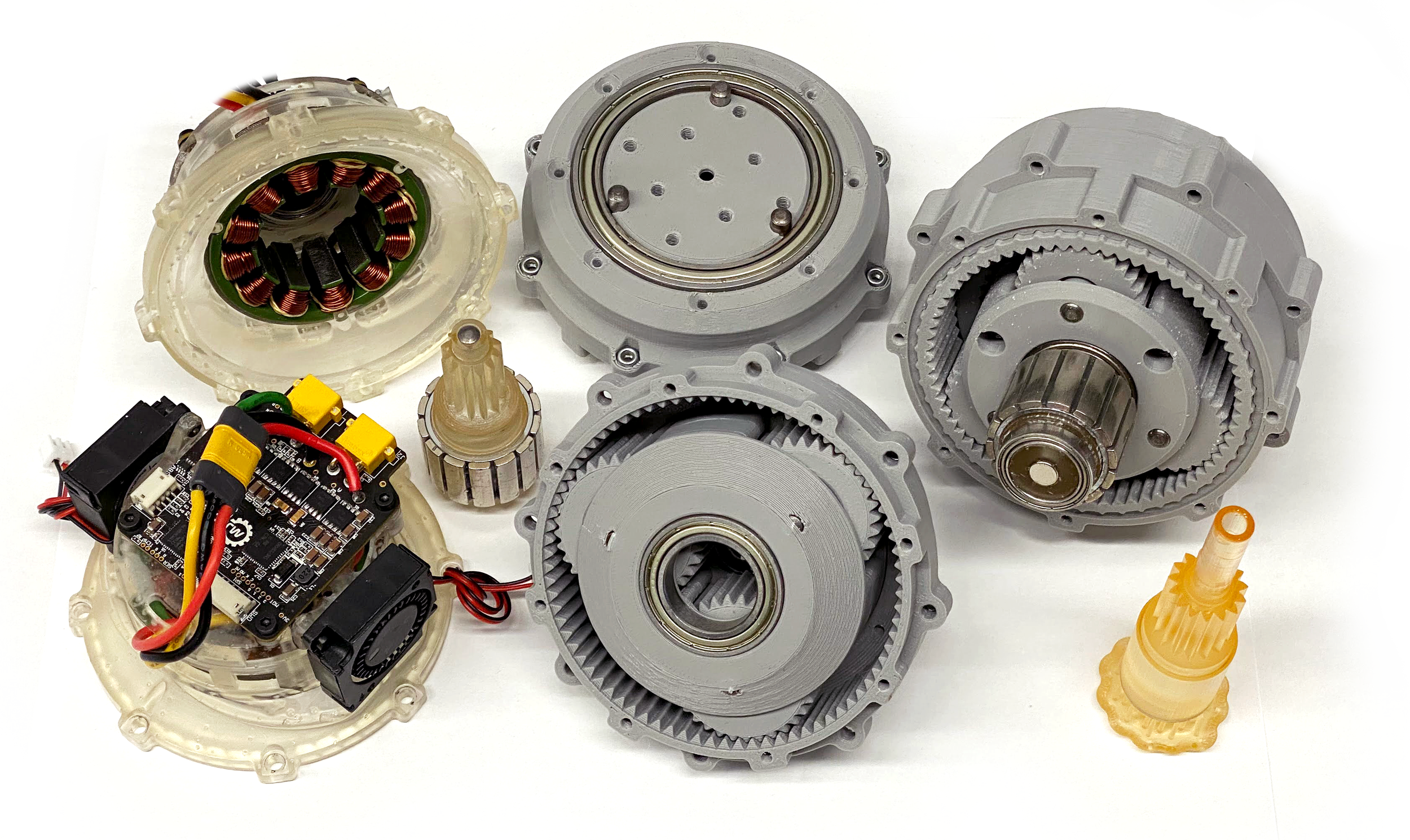
3DP Actuator
Assembly Guide
By Mirielle Wong, modified 2023.04.19
Planetary Actuator 7.5:1
Note: Print all STLs with supports
Planet Carrier Assembly
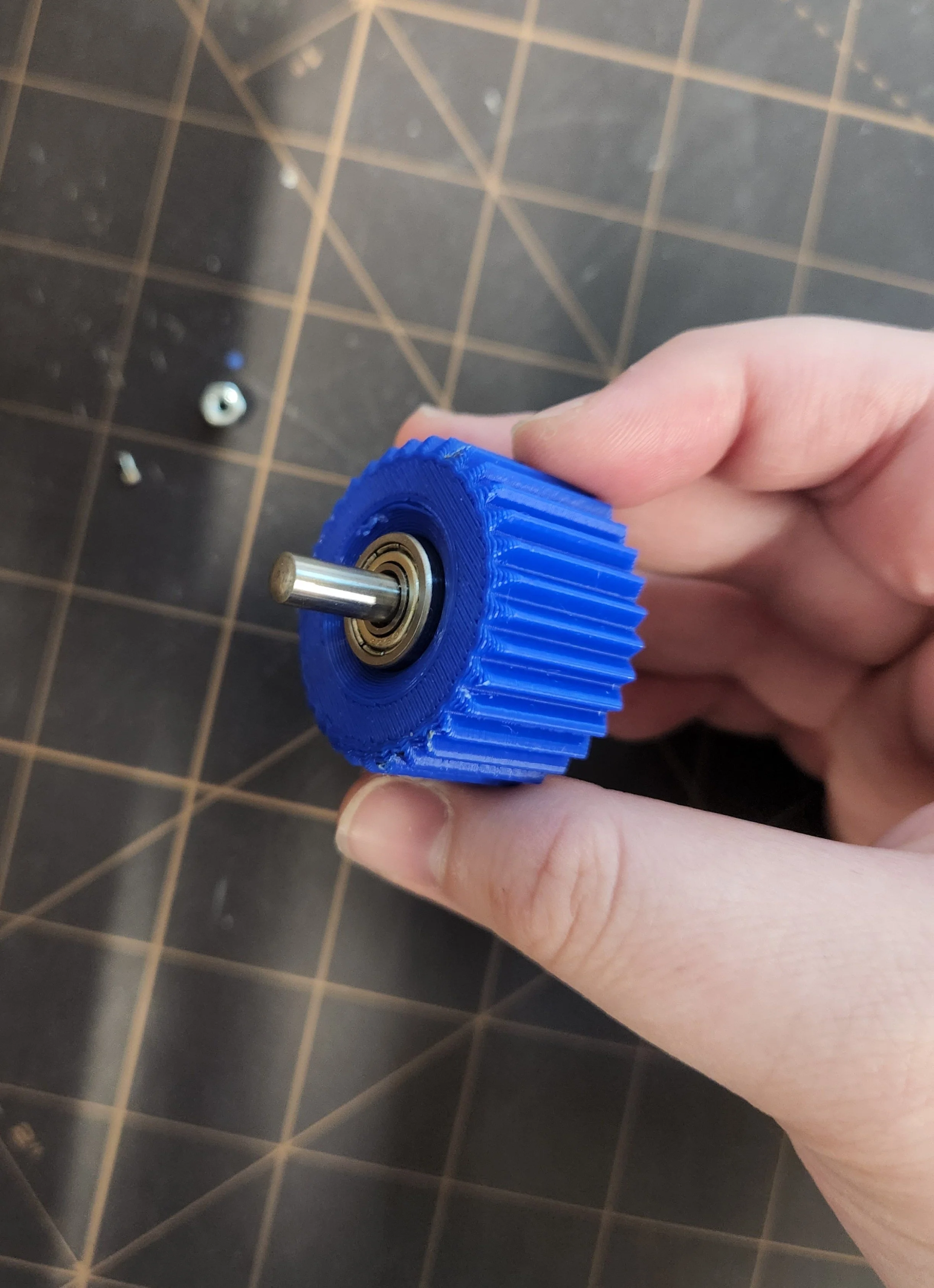
Take two 5mm ID bearings and one planet gear, as shown. Press one washer on either side of the planet gear. They should press fit into the inner contour of the planet gear.
Repeat for each planet gear.
For each planet gear, press a 5mm x 25mm dowel pin through the gear axis. The dowel pins should stick out approximately equally on both sides of the gear, and the gear should spin around the axis easily.
Press the 20mm ID bearing into the planet carrier input side. It should fit the contour of the piece.
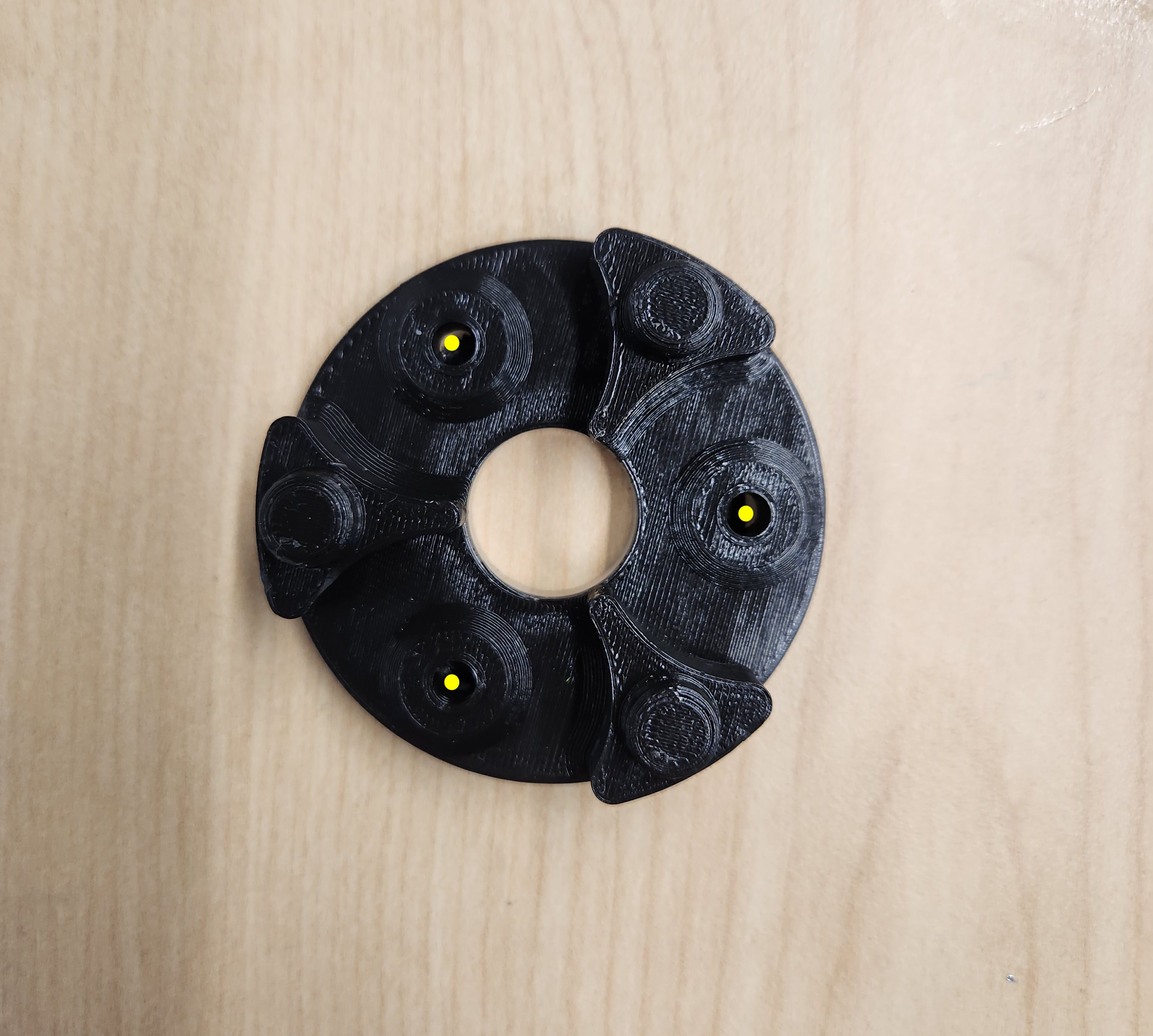
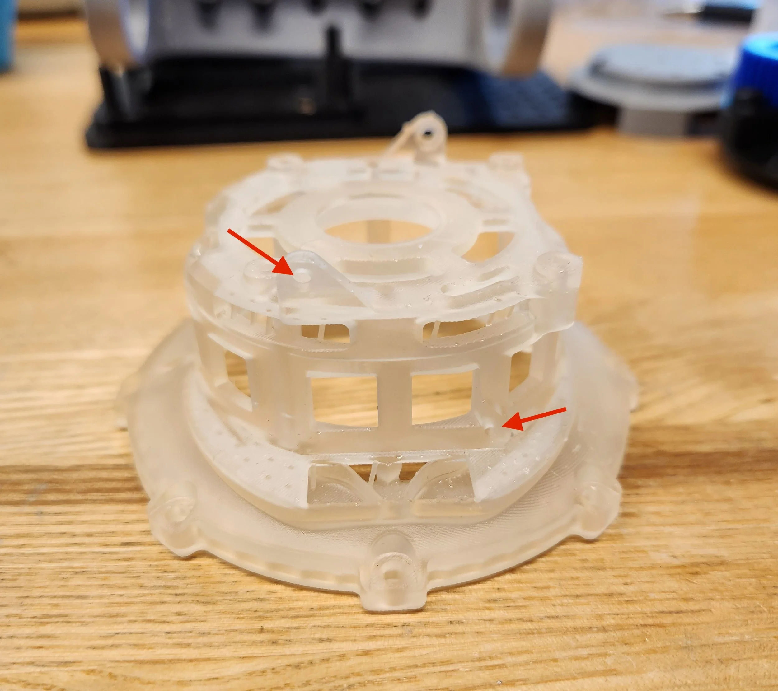
Insert the gears into the planet carrier input side by placing the planet carrier input side as shown in the image and pressing the dowel pins into the three indicated holes. It’s fine if the dowel pins break the thin covering, but don’t let them extrude too much from the PLA.
Press the 8mm ID bearing into the space in the center of the planet carrier output side.
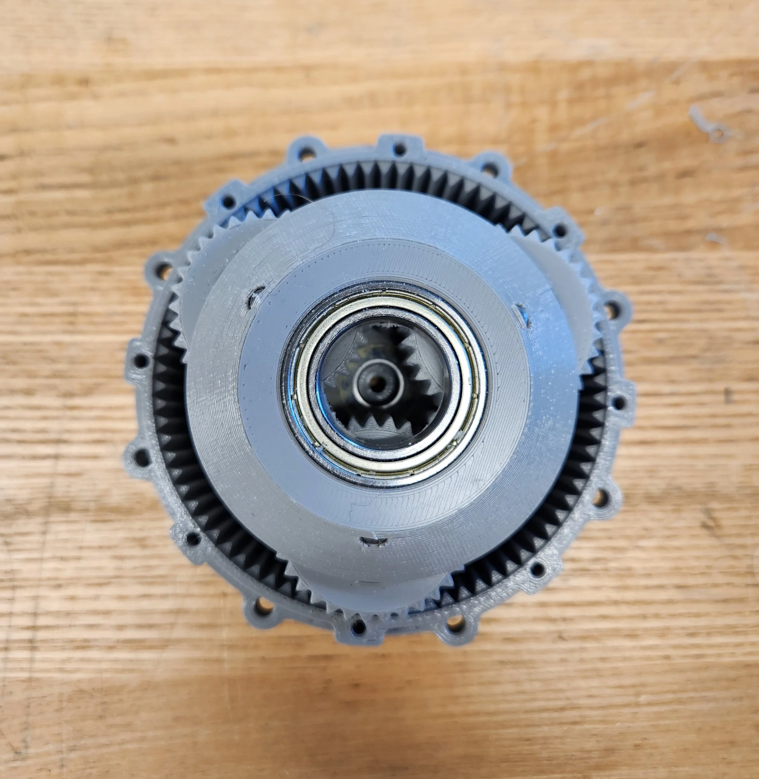
Place the planet carrier output side on top of the gears. Push the dowel pins through the holes and press until you hear the two planet carrier parts snap into place. The photo below shows the side view of the pressfit with only one planet gear inserted for visibility, but you should have all three inserted.
We have finished assembling the planet carrier.
Fit the planet carrier into the correct planetary output housing for the link you are assembling (Links 1 and 3 actuator mounts shown in photos).
Rotor Assembly
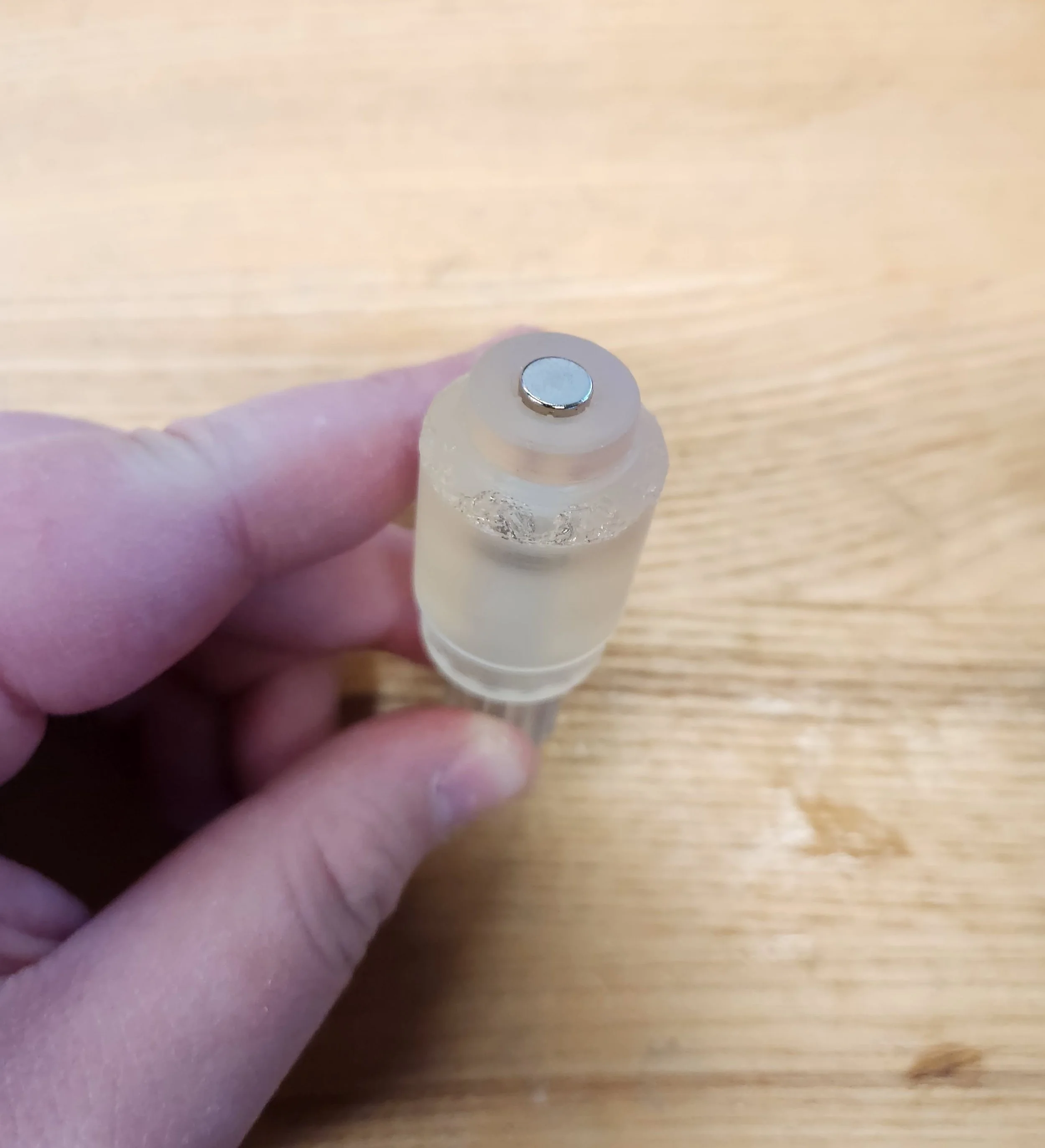
Sand the hole for the axial dowel pin so that it extends approximately halfway down the piece and the radius is wide enough for the 40mm dowel pin.
Push the dowel pin into the sun rotor until the corner of the dowel pin aligns with the edge of the sun rotor opening.
Glue a neodymium magnet to the base of the sun rotor.
Motor Housing and Moteus Board
Make sure the planetary housing is well sanded so the edges are well defined.
We will be press fitting the motor into the actuator housing, but first make sure the cords are wired through the slots in the housing so they can be plugged into the moteus board.
Carefully press fit the motor into the actuator housing.
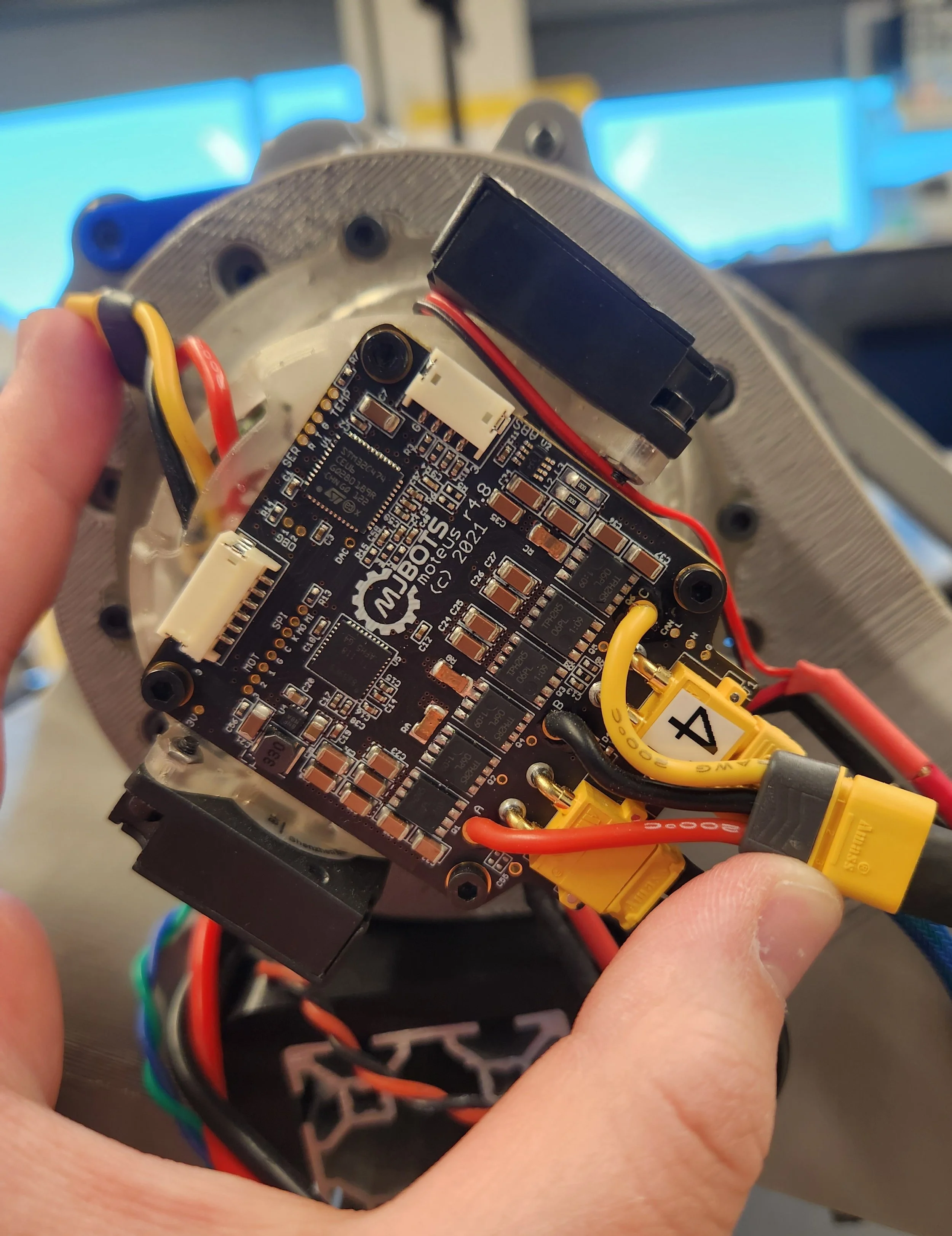
Attach the moteus board on top using four M3 screws.
Attach the fans to the sides of the housing using two M2 screws in the spots shown in the photo.
Plug in the cables from the motor to the moteus board, and the fans into the moteus board.
Last Actuator Assembly Steps
Insert the sun rotor into the motor (it should magnetically snap into place). Attach the output housing by aligning the inner planet gears with the teeth of the sun rotor and pushing the two halves together.
Fasten together the motor and the output housing using M3x12 screws in the holes around the edge of the motor housing.
If necessary, attach the heat sink above the moteus board. This is only necessary for actuators that are in danger of overheating.

